Introduction
In this tutorial, we'll be creating a mask effect using geometry nodes. The Mask Geometry Node lets you create masks with masks! You can use them to put an image on top of your 3D objects to make them appear as though they are wearing an outfit or just have different colors applied to their faces.
The Mask Geometry Node
The Mask Geometry node is a great way to create mask effects. This node can be used in a variety of ways, from creating simple black and white masks to complex scenes with many layers.
The Mask Geometry can be used for all kinds of things:
Creating custom shapes for your project (like you might do with the Curvature or Fractional Spline)
Making simple edge masks around objects like this one (but without any transparency)
Blender Mask Effect Tutorial
Mask effects are an animation that is used to hide or show part of an object. Masking is useful for creating a variety of visual effects, such as hiding or showing parts of characters and objects in 3D scenes.
In this tutorial we'll learn how to create a mask effect using geometry nodes in Blender 3D software!
Example #1: Using the Mask Geometry Node to Create a Mask
For example, if you have a mesh that has some geometry and materials applied to it, you can use the mask geometry node to create a mask for an object or material. You can also use this method for creating masks for different parts of an object or material.
To create a mask for your object:
Select your object in the 3D viewport
In Vertex section, enable Mask Geometry Node checkbox at Viewport Filter level
Example #2: Adding a Mask to an Object
In this example, we are going to use the mask geometry node to create a mask of our object. To do this, we need to create a different mesh inside of the same object. In this case, I created another cube that will be used as my source mesh for our newly created mask. Then I copy-paste it into my other cube and then rename it “mask” (and make sure its parent is set to my original cube).
Now let’s go back into Blender 3D and select both cubes so that we can see their names in the top left corner of Blender 3D (screenshot below). You should also notice that when you hover over these two objects there is an arrow pointing toward each one which indicates what layer they are located at in Blender 3D's scene hierarchy hierarchy
Example #3: Creating a Material from a Material Expression
This example is based on the same material as in Example #1. The difference is that we now have an additional node called Material Expression, which allows us to use the value from another node as a property of our material.
In this case, we're creating a material from another material expression:
```Blender 3D object: ```
This tutorial will show you how to create mask effects using geometry nodes in blender 3d.
A mask is a 2D image that you can use to hide or reveal parts of another object.
Mask effects are commonly used in 3D animation, but they can also be used in games and other applications.
In this tutorial we’ll show how to create masks using geometry nodes in blender 3d.
Conclusion
You've seen them in movies, on TV and online. You might even have your own mask effect that you've been working on for a while. But what exactly is a mask? And how do we make one in Blender? We'll take a look at both here!
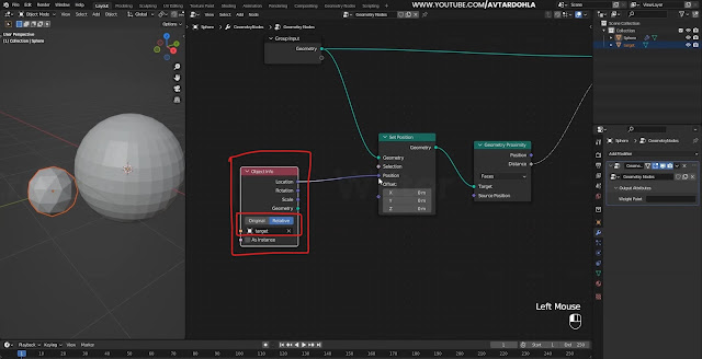
Here is the complete Nodes setup you can see in one view and Easley to understanding.
I will show you how we use in video, I hope you like this, If you have any questions
drop your comments in below.
Complete Nodes Setup
Note:- This new geometry nodes system in only blender updated versions, please update it
1. Add a (Sphere and Ico Sphere) in 3D Viewport
- Select (Sphere) then add these nodes 👇
Data Properties & Make a New Vertex Group + 👇
or Watch in Depth Tutorial 👉 Watch Now
(like 0.1) Smoothness Repeat (10 times) 👇
then set Multiply---Scale---Multiply 👇
or Watch in Depth Tutorial 👉 Watch Now


0 Comments